-
Limit E (dBµV/m) at frequency F (MHz)
3
 0-75
MHz
0-75
MHz75-400 MHz
400-1,000 MHz
E = 32
E = 32 + 15.13 log (F/75)
E = 43

|
|
Maximum allowed pulse amplitude for |
|
|
Polarity of pulse amplitude |
Vehicles with 12 V systems |
Vehicles with 24 V systems |
|
Positive |
+75 V |
+150 V |
|
Negative |
–100 V |
–450 V |
|
Test pulse number |
Immunity test level |
Functional status for systems: |
|
|
Related to immunity related functions |
Not related to immunity related functions |
||
|
1 |
III |
C |
D |
|
2a |
III |
B |
D |
|
2b |
III |
C |
D |
|
3a/3b |
III |
A |
D |
|
4 |
III |
B (for ESA which shall be operational during engine start phases) C (for other ESA) |
D |
|
Harmonic number n |
Maximum authorized harmonic current A |
|
Odd harmonics |
|
|
3 |
2.3 |
|
5 |
1.14 |
|
7 |
0.77 |
|
9 |
0.40 |
|
11 |
0.33 |
|
13 |
0.21 |
|
15 ≤ n ≤ 39 |
0.15x15/n |
|
Even harmonics |
|
|
2 |
1.08 |
|
4 |
0.43 |
|
6 |
0.30 |
|
8 ≤ n ≤ 40 |
0.23x8/n |
|
Minimum Rsce |
Acceptable
individual harmonic current In/I1 |
Maximum
current harmonic ratio |
||||||
|
|
I3 |
I5 |
I7 |
I9 |
I11 |
I13 |
THD |
PWHD |
|
33 |
21.6 |
10.7 |
7.2 |
3.8 |
3.1 |
2 |
23 |
23 |
|
66 |
24 |
13 |
8 |
5 |
4 |
3 |
26 |
26 |
|
120 |
27 |
15 |
10 |
6 |
5 |
4 |
30 |
30 |
|
250 |
35 |
20 |
13 |
9 |
8 |
6 |
40 |
40 |
|
≥ 350 |
41 |
24 |
15 |
12 |
10 |
8 |
47 |
47 |
|
Relative values of even harmonics lower or equal to 12 shall be lower than 16/n %. Even harmonics greater than 12 are taken into account in the Total Harmonic Distorsion (THD) and Partial Weighted Harmonic Distorsion (PWHD) the same way than odd harmonics. Linear interpolation between successive values of Short Circuit Ratio of an Equipment (Rsce) is authorized. |
||||||||
|
Minimum Rsce |
Acceptable
individual harmonic current In/I1 |
Maximum
current harmonic ratio |
||||
|
|
I5 |
I7 |
I11 |
I13 |
THD |
PWHD |
|
33 |
10.7 |
7.2 |
3.1 |
2 |
13 |
22 |
|
66 |
14 |
9 |
5 |
3 |
16 |
25 |
|
120 |
19 |
12 |
7 |
4 |
22 |
28 |
|
250 |
31 |
20 |
12 |
7 |
37 |
38 |
|
≥ 350 |
40 |
25 |
15 |
10 |
48 |
46 |
|
Relative values of even harmonics lower or equal to 12 shall be lower than 16/n %. Even harmonics greater than 12 are taken into account in the THD and PWHD the same way than odd harmonics. Linear interpolation between successive values of Rsce is authorized. |
||||||
|
Minimum Rsce |
Acceptable individual harmonic current In/I1 % |
Maximum current harmonic ratio % |
||||
|
|
I5 |
I7 |
I11 |
I13 |
THD |
PWHD |
|
33 |
10.7 |
7.2 |
3.1 |
2 |
13 |
22 |
|
≥ 120 |
40 |
25 |
15 |
10 |
48 |
46 |
|
Relative values of even harmonics lower or equal to 12 shall be lower than 16/n %. Even harmonics greater than 12 are taken into account in the THD and PWHD the same way than odd harmonics |
||||||
|
Frequency (MHz) |
Limits and detector |
|
0.15 to 0.5 |
66 to 56 dBµV (quasi-peak) 56 to 46 dBµV (average) (linearly decreasing with logarithm of frequency) |
|
0.5 to 5 |
56 dBµV (quasi-peak) 46 dBµV (average) |
|
5 to 30 |
60 dBµV (quasi-peak) 50 dBµV (average) |
|
Frequency (MHz) |
Limits and detector |
|
0.15 to 0.5 |
79 dBµV (quasi-peak) 66 dBµV (average) |
|
0.5 to 30 |
73 dBµV (quasi-peak) 60 dBµV (average) |
|
Frequency (MHz) |
Voltage limits (detector) |
Current limits (detector) |
|
0.15 to 0.5 |
84 to 74 dBµV (quasi-peak) 74 to 64 dBµV (average) |
40 to 30 dBµA (quasi-peak) 30 to 20 dBµA (average) |
|
0.5 to 30 |
74 dBµV (quasi-peak) 64 dBµV (average) |
30 dBµA (quasi-peak) 20 dBµA (average) |
|
Harmonic number n |
Maximum authorized harmonic current A |
|
Odd harmonics |
|
|
3 |
2.3 |
|
5 |
1.14 |
|
7 |
0.77 |
|
9 |
0.40 |
|
11 |
0.33 |
|
13 |
0.21 |
|
15 ≤ n ≤ 39 |
0.15x15/n |
|
Even harmonics |
|
|
2 |
1.08 |
|
4 |
0.43 |
|
6 |
0.30 |
|
8 ≤ n ≤ 40 |
0.23x8/n |
|
Minimum Rsce |
Acceptable individual harmonic current In/I1 % |
Maximum current harmonic ratio % |
||||||
|
I3 |
I5 |
I7 |
I9 |
I11 |
I13 |
THD |
PWHD |
|
|
33 |
21.6 |
10.7 |
7.2 |
3.8 |
3.1 |
2 |
23 |
23 |
|
66 |
24 |
13 |
8 |
5 |
4 |
3 |
26 |
26 |
|
120 |
27 |
15 |
10 |
6 |
5 |
4 |
30 |
30 |
|
250 |
35 |
20 |
13 |
9 |
8 |
6 |
40 |
40 |
|
≥ 350 |
41 |
24 |
15 |
12 |
10 |
8 |
47 |
47 |
|
Relative values of even harmonics lower or equal to 12 shall be lower than 16/n %. Even harmonics greater than 12 are taken into account in the THD and PWHD in the same way than odd harmonics. Linear interpolation between successive values of Rsce is authorized. |
||||||||
|
Minimum Rsce |
Acceptable individual harmonic current In/I1 % |
Maximum current harmonic ratio % |
||||
|
I5 |
I7 |
I11 |
I13 |
THD |
PWHD |
|
|
33 |
10.7 |
7.2 |
3.1 |
2 |
13 |
22 |
|
66 |
14 |
9 |
5 |
3 |
16 |
25 |
|
120 |
19 |
12 |
7 |
4 |
22 |
28 |
|
250 |
31 |
20 |
12 |
7 |
37 |
38 |
|
≥ 350 |
40 |
25 |
15 |
10 |
48 |
46 |
|
Relative values of even harmonics lower or equal to 12 shall be lower than 16/n %. Even harmonics greater than 12 are taken into account in the THD and PWHD in the same way as odd harmonics. Linear interpolation between successive values of Rsce is authorized. |
||||||
|
Minimum Rsce |
Acceptable individual harmonic current In/I1 % |
Maximum current harmonic ratio % |
||||
|
I5 |
I7 |
I11 |
I13 |
THD |
PWHD |
|
|
33 |
10.7 |
7.2 |
3.1 |
2 |
13 |
22 |
|
≥ 120 |
40 |
25 |
15 |
10 |
48 |
46 |
|
Relative values of even harmonics lower or equal to 12 shall be lower than 16/n %. Even harmonics greater than 12 are taken into account in the THD and PWHD in the same way as odd harmonics. |
||||||
|
Frequency (MHz) |
Limits and detector |
|
0.15 to 0.5 |
66 to 56 dBµV (quasi-peak) (linearly decreasing with logarithm of frequency) |
|
0.5 to 5 |
56 dBµV (quasi-peak) |
|
5 to 30 |
60 dBµV (quasi-peak) |
|
Frequency (MHz) |
Limits and detector |
|
0.15 to 0.5 |
79 dBµV (quasi-peak) |
|
0.5 to 30 |
73 dBµV (quasi-peak) |
|
Frequency (MHz) |
Voltage limits (detector) |
Current limits (detector) |
|
0.15 to 0.5 |
84 to 74 dBµV (quasi-peak) (linearly decreasing with |
40 to 30 dBµA (quasi-peak) (linearly decreasing with |
|
0.5 to 30 |
74 dBµV (quasi-peak) |
30 dBµA (quasi-peak) |
|
|
Maximum allowed pulse amplitude for |
|
|
Polarity of pulse amplitude |
Vehicles with 12 V systems |
Vehicles with 24 V systems |
|
Positive |
+75 V |
+150 V |
|
Negative |
–100 V |
–450 V |
|
Test pulse number |
Immunity test level |
Functional status for systems: |
|
|
Related to immunity related functions |
Not related to immunity related functions |
||
|
1 |
III |
C |
D |
|
2a |
III |
B |
D |
|
2b |
III |
C |
D |
|
3a/3b |
III |
A |
D |
|
4 |
III |
B (for ESA which shall be operational during engine start phases) C (for other ESA) |
D |
|
Limit E (dBµV/m) at frequency F (MHz) |
||
|
3 |
75-400 MHz |
400-1,000 MHz |
|
E = 32 |
E = 32 + 15.13 log (F/75) |
E = 43 |
|
Limit E (dBµV/m) at frequency F (MHz) |
||
|
30-75 MHz |
75-400 MHz |
400-1,000 MHz |
|
E = 42 |
E = 42 + 15.13 log (F/75) |
E = 53 |
|
Limit E (dBµV/m) at frequency F (MHz) |
||
|
30-75 MHz |
75-400 MHz |
400-1,000 MHz |
|
E = 22 |
E = 22 + 15.13 log (F/75) |
E = 33 |
|
Limit E (dBµV/m) at frequency F (MHz) |
||
|
30-75 MHz |
75-400 MHz |
400-1,000 MHz |
|
E = 32 |
E = 32 + 15.13 log (F/75) |
E = 43 |
|
Limit E (dBµV/m) at frequency F (MHz) |
||
|
30-75 MHz |
75-400 MHz |
400-1,000 MHz |
|
E = 62 - 25.13 log (F/30) |
E = 52 + 15.13 log (F/75) |
E = 63 |
|
Limit E (dBµV/m) at frequency F (MHz) |
||
|
30-75 MHz |
75-400 MHz |
400-1,000 MHz |
|
E = 52 - 25.13 log (F/30) |
E = 42 + 15.13 log (F/75) |
E = 53 |
|
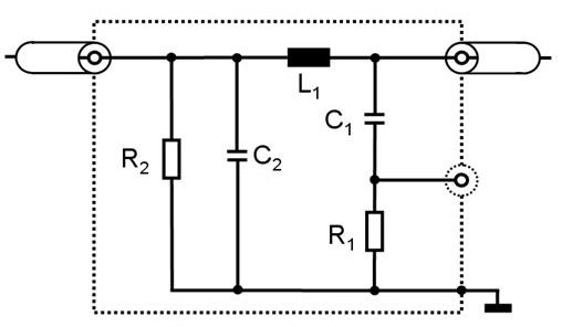
Legend |
C2: 0.1 µF |
|
L1: 5 µH |
R1: 1 kΩ |
|
C1: 0.1 µF |
R2: 1 MΩ (discharging C2 to < 50 Vdc within 60 s) |
|
|
|
|
|
Frequency bands [Hz] |
Max. output power [W] |
Antenna position at
vehicle, |

|
Frequency
range |
Peak detector |
Quasi-peak detector |
Average detector |
|||
|
RBW at |
Scan |
RBW at |
Scan |
RBW at |
Scan |
|
|
30
to |
100/120 kHz |
100 ms/MHz |
120 |
20 |
100/120 kHz |
100 ms/MHz |
|
Frequency
range |
Peak detector |
Quasi-peak detector |
Average detector |
||||||
|
BW at |
Step |
Dwell time |
BW at |
Step |
Dwell time |
BW at |
Step |
Dwell time |
|
|
30 to 1,000 |
120 kHz |
50 |
5 |
120 |
50 |
1 |
120 |
50 |
5 |
|
Frequency
range |
Peak detector |
Quasi-peak detector |
Average detector |
|||
|
RBW at |
Scan |
RBW at |
Scan |
RBW at |
Scan |
|
|
30 to 1,000 |
100/120 kHz |
100 ms/MHz |
120 kHz |
20 s/MHz |
100/120 kHz |
100 ms/MHz |
|
Frequency
range |
Peak detector |
Quasi-peak detector |
Average detector |
||||||
|
BW
at |
Step |
Dwell time |
BW
at |
Step |
Dwell time |
BW
at |
Step |
Dwell time |
|
|
30 to 1,000 |
120 kHz |
50 kHz |
5 |
120 kHz |
50 kHz |
1 |
120 kHz |
50 kHz |
5 |
|
"50 km/h cycle" vehicle test conditions |
Failure criteria |
|
Vehicle speed 50 km/h (respectively 25 km/h for L1, L2 vehicles) 20 per cent (vehicle driving the rollers). If the vehicle is equipped with a cruise control system, it shall be operational. |
Speed variation greater than 10 per cent of the nominal speed. In case of automatic gearbox: change of gear ratio inducing a speed variation greater than 10 per cent of the nominal speed. |
|
Dipped beams ON (manual mode) |
Lighting OFF |
|
Front wiper ON (manual mode) maximum speed |
Complete stop of front wiper |
|
Direction indicator on driver's side ON |
Frequency change (lower than 0.75 Hz or greater than 2.25 Hz). Duty cycle change (lower than 25 per cent or greater than 75 per cent). |
|
Adjustable suspension in normal position |
Unexpected significant variation |
|
Driver's seat and steering wheel in medium position |
Unexpected variation greater than 10 per cent of total range |
|
Alarm unset |
Unexpected activation of alarm |
|
Horn OFF |
Unexpected activation of horn |
|
Airbag and safety restraint systems operational with inhibited passenger airbag if this function exists |
Unexpected activation |
|
Automatic doors closed |
Unexpected opening |
|
Adjustable endurance brake lever in normal position |
Unexpected activation |
|
"Brake cycle" vehicle test conditions |
Failure criteria |
|
To be defined in brake cycle test plan. This shall include operation of the brake pedal (unless there are technical reasons not to do so) but not necessarily an anti-lock brake system action. |
Stop
lights inactivated during cycle |
|
"REESS charging mode" vehicle test conditions |
Failure criteria |
|
The REESS shall be in charging mode. The REESS State of charge (SOC) shall be kept between 20 per cent and 80 per cent of the maximum SOC during the whole frequency range measurement (this may lead to split the measurement in different sub-bands with the need to discharge the vehicle's traction battery before starting the next sub-bands). If the current consumption can be adjusted, then the current shall be set to at least 20 per cent of its nominal value. |
Vehicle sets in motion. |
|
Frequency
range |
Peak detector |
Quasi-peak detector |
Average detector |
|||
|
RBW at |
Scan |
RBW at |
Scan |
RBW at |
Scan |
|
|
30 to 1,000 |
100/120 kHz |
100 ms/MHz |
120 kHz |
20 s/MHz |
100/120 kHz |
100 ms/MHz |
|
Frequency
range |
Peak detector |
Quasi-peak detector |
Average detector |
||||||
|
BW
at |
Step |
Dwell time |
BW
at |
Step |
Dwell time |
BW
at |
Step |
Dwell time |
|
|
30 to 1,000 |
120 Hz |
50 kHz |
5 ms |
120 Hz |
50 kHz |
1 s |
120 kHz |
50 kHz |
5 ms |
|
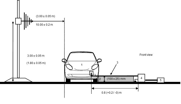
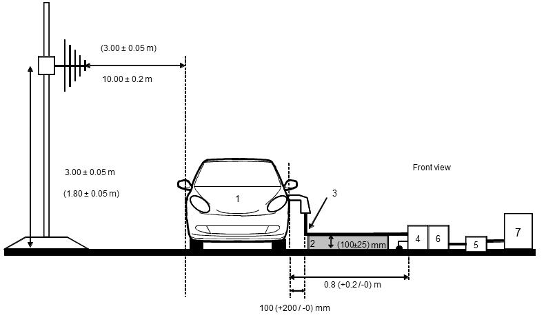
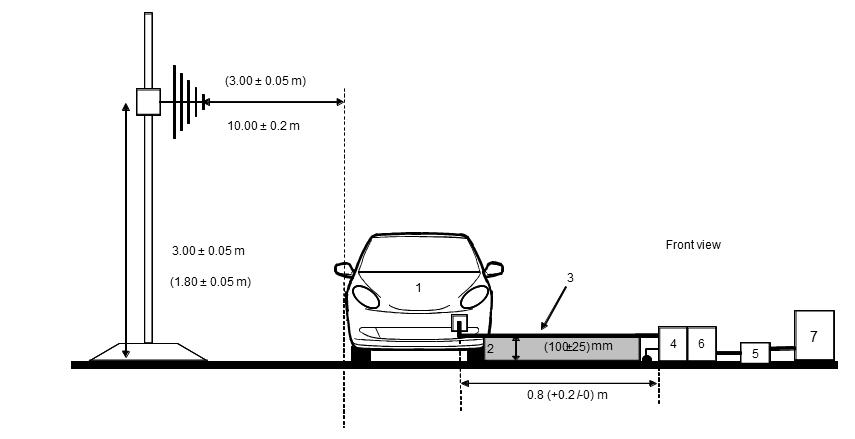
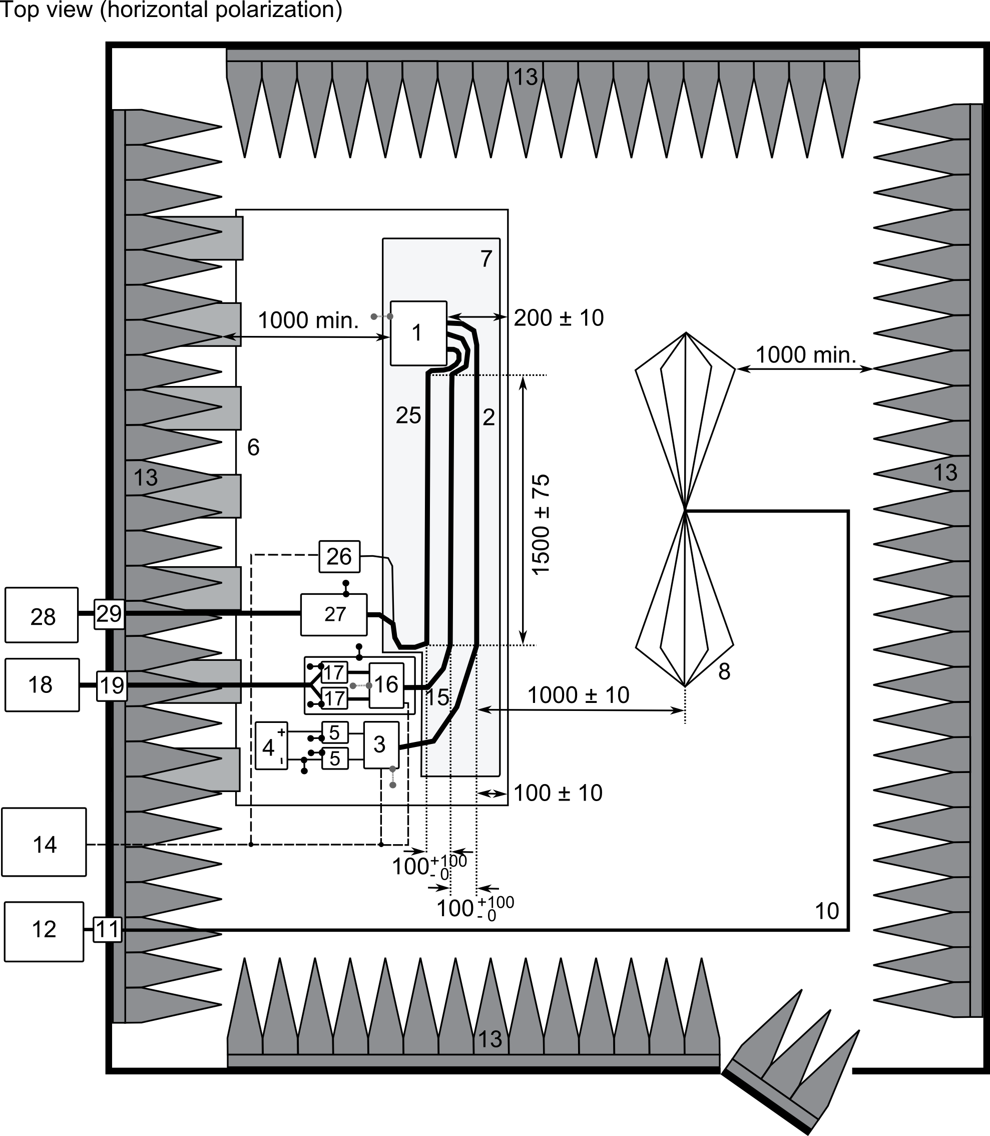
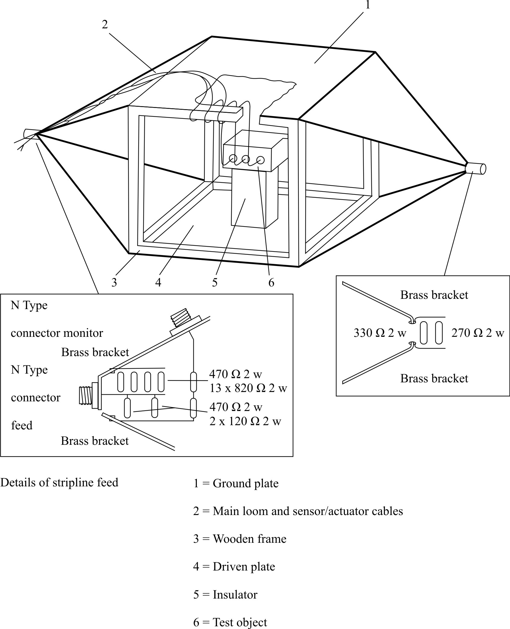
Legend: 1 ESA (grounded locally if required in test plan) 2 LV Test harness 3 LV Load simulator (placement and ground connection according to CISPR 25 paragraph 6.4.2.5) 4 Power supply (location optional) 5 LV Artificial network (AN) 6 Ground plane (bonded to shielded enclosure) 7 Low relative permittivity support (εr ≤ 1.4) 8 Biconical antenna 10 High-quality coaxial cable e.g. double-shielded (50 Ω) 11 Bulkhead connector 12 Measuring instrument
|
13 RF absorber material 14 Stimulation and monitoring system 15 HV harness 16 HV load simulator 17 HV AN 18 HV power supply 19 HV feed-through 25 AC/DC charger harness 26 AC/DC load simulator (e.g. Programmable Logic Controller (PLC)) 27 50µH Line Impedance Stabilization Network (LISN) (AC) or HVAN (DC) 28 AC/DC power supply 29 AC/DC feed-through |
|
Frequency
range |
Peak detector |
Quasi-peak detector |
Average detector |
|||
|
RBW
at |
Scan |
RBW
at |
Scan
|
RBW
at |
Scan |
|
|
30 to 1,000 |
100/120 kHz |
100 ms/MHz |
120 kHz |
20 s/MHz |
100/120 kHz |
100 ms/MHz |
|
Frequency
range |
Peak detector |
Quasi-peak detector |
Average detector |
||||||||
|
BW at |
Step |
Dwell time |
BW at |
Step |
Dwell time |
BW at |
Step |
Dwell time |
|||
|
30 to 1,000 |
120 kHz |
50 kHz |
5 ms |
120 kHz |
50 kHz |
1 s |
120 kHz |
50 kHz |
5 ms |
||
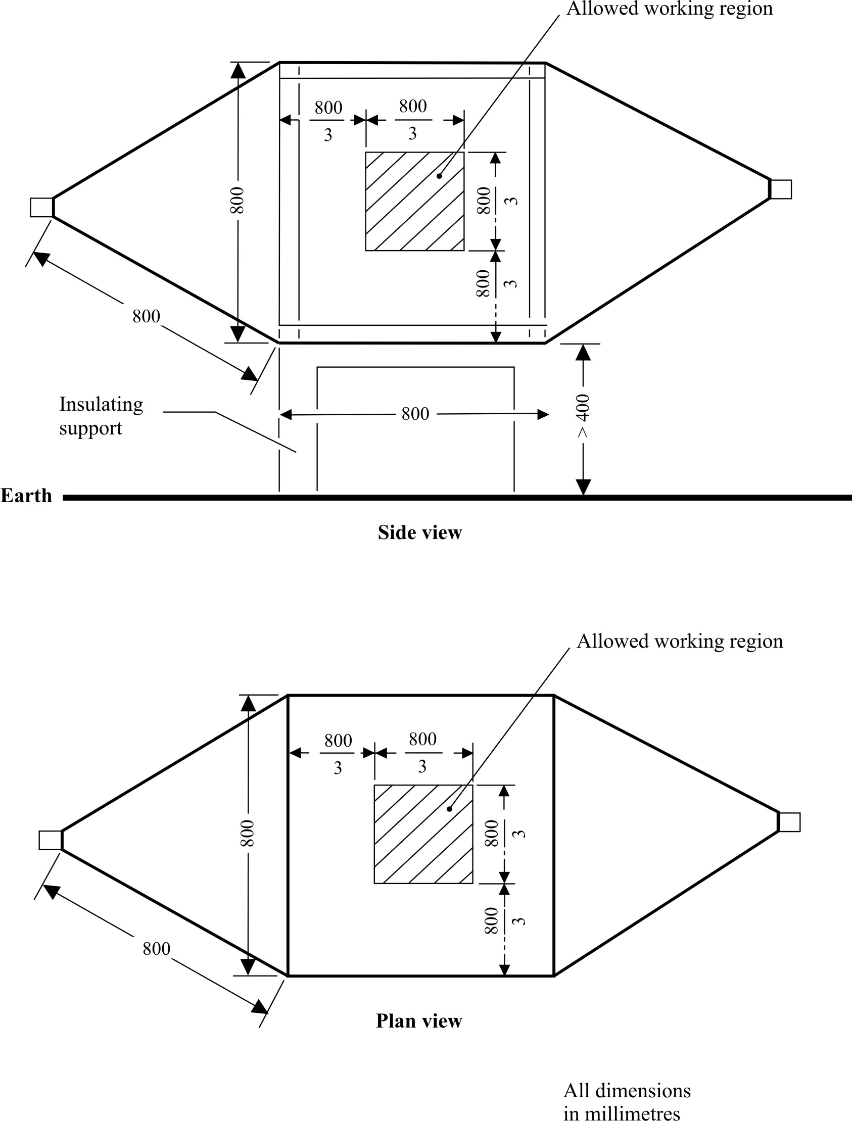
|
Upper frequency |
Cell
form factor |
Cell
form factor |
Plate
separation |
Septum
|
|
200 200 |
1.69 1.00 |
0.66 1 |
56 60 |
70 50 |
|
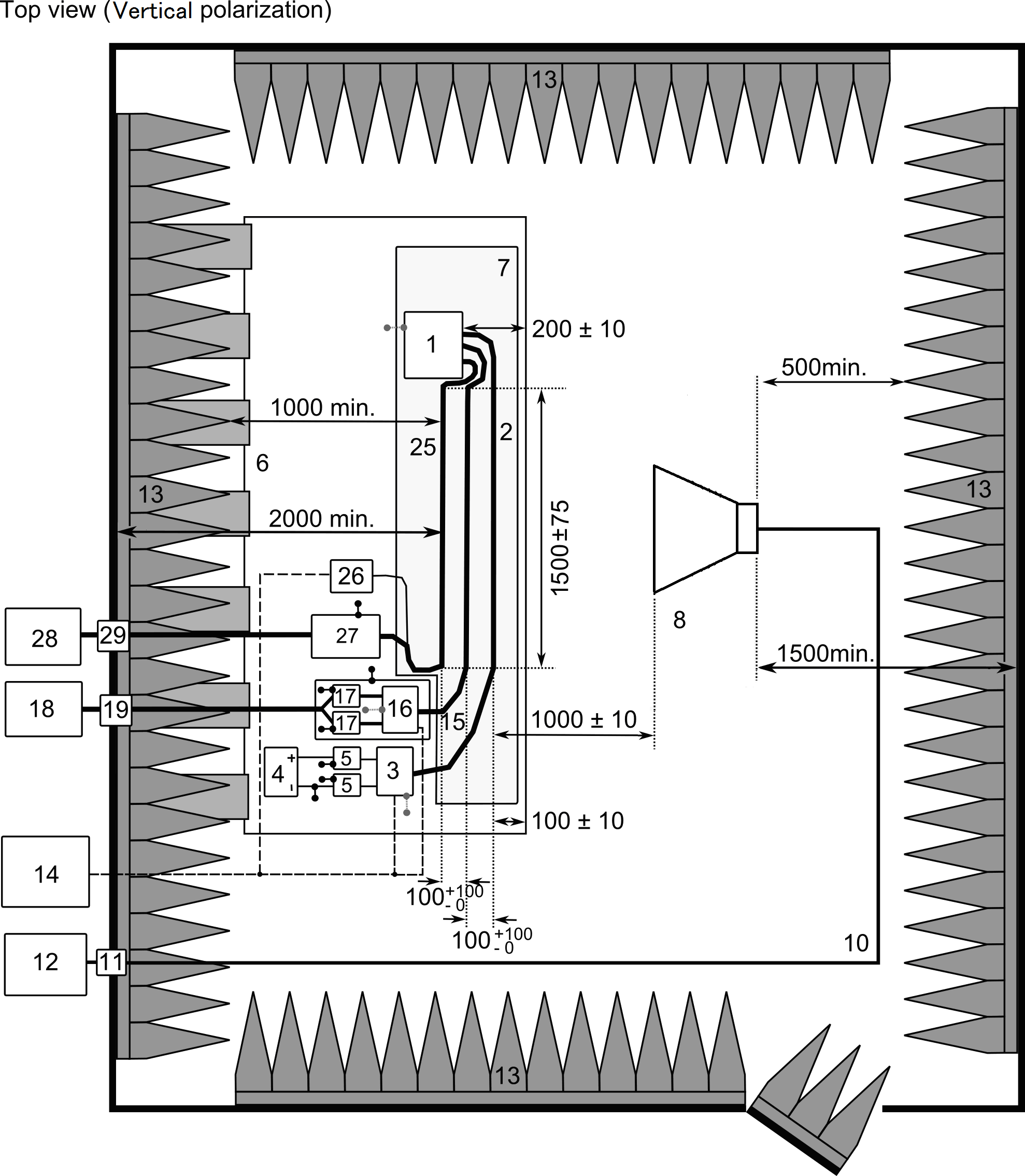
Legend: 1 ESA (grounded locally if required in test plan) 2 LV Test harness 3 LV Load simulator (placement and ground connection according to CISPR 25 paragraph 6.4.2.5.) 4 Power supply (location optional) 5 LV Artificial network (AN) 6 Ground plane (bonded to shielded enclosure) 7 Low relative permittivity support (εr ≤ 1.4) 8 Horn antenna 10 High-quality coaxial cable e.g. double-shielded (50 Ω) 11 Bulkhead connector 12 RF signal generator and amplifier
|
13 RF absorber material 14 Stimulation and monitoring system 15 HV harness 16 HV load simulator 17 HV AN 18 HV power supply 19 HV feed-through 25 AC/DC charger harness 26 AC/DC load simulator (e.g. PLC) 27 50µH LISN (AC) or HVAN (DC) 28 AC/DC power supply 29 AC/DC feed-through |
|
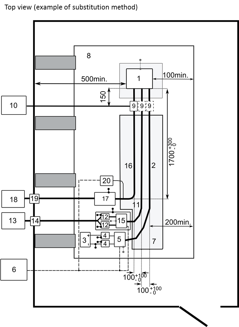
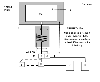
Legend: 1 ESA (grounded locally if required in test plan) 2 LV Test harness 3 LV supply 4 LV LISN 5 LV load simulator 6 Stimulation and monitoring system 7 Low relative permittivity support 8 Ground plane 9 Injection probe 10 RF signal amplifier and generator |
11 HV DC harness 12 HV AN 13 HV DC load 14 HV DC feed-through 15 HV DC load simulator 16 HV AC/DC charger harness 17 50 µH LISN (AC) or HV AN (DC) 18 HV AC/DC power supply 19 HV AC/DC feed-through 20 HV AC/DC load simulator (e.g. PLC) |
|
Frequency
range |
Peak detector |
Quasi-peak detector |
Average detector |
|||
|
RBW at |
Scan |
RBW at |
Scan |
RBW at |
Scan |
|
|
0.15 to 30 |
9/10 kHz |
10 s/MHz |
9 kHz |
200 s/MHz |
9/10 kHz |
10 s/MHz |
|
Frequency range |
Peak detector |
Quasi-peak detector |
Average detector |
||||||
|
BW
at |
Step |
Dwell time |
BW
at |
Step |
Dwell time |
BW
at |
Step |
Dwell time |
|
|
0.15 to 30 |
9 kHz |
5 kHz |
50 ms |
9 kHz |
5 kHz |
1 s |
9 kHz |
5 kHz |
50 ms |
|
Frequency
range |
Peak detector |
Quasi-peak detector |
Average detector |
|||
|
RBW at |
Scan |
RBW at |
Scan |
RBW at |
Scan |
|
|
0.15 to 30 |
9/10 |
10 |
9 |
200 s/MHz |
9/10 |
10 |
|
Frequency range |
Peak detector |
Quasi-peak detector |
Average detector |
||||||
|
BW at |
Step |
Dwell time |
BW at |
Step |
Dwell time |
BW at |
Step |
Dwell time |
|
|
0.15 to 30 |
9 |
5 |
50 |
9 |
5 |
1 |
9 |
5 |
50 |
|
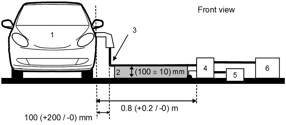
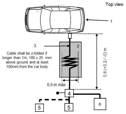
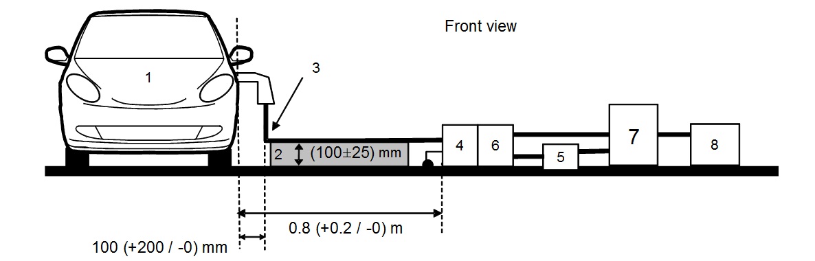
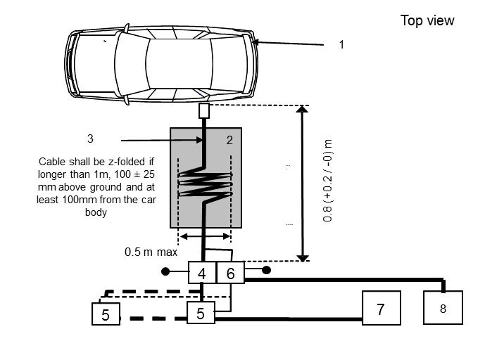
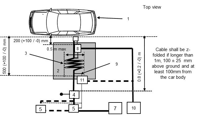
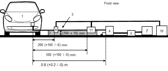
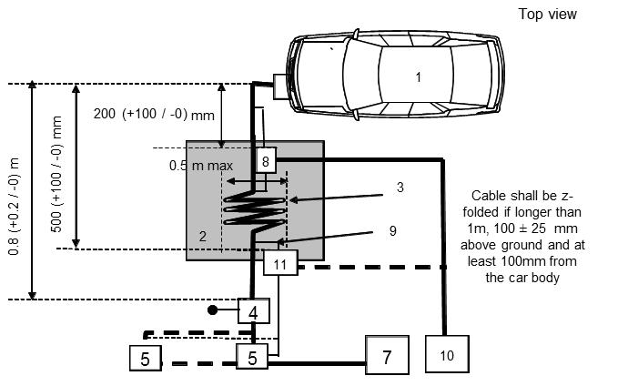
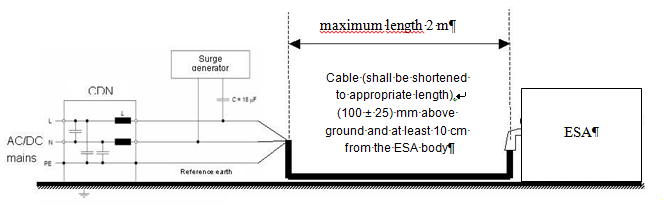
Legend: 1 Vehicle under test 2 Insulating support 3 Charging / communication cable 4 AC or DC artificial network(s) grounded (for AC or DC power lines) |
5 Power mains socket 6 Impedance stabilization(s) grounded (for communication lines) 7 Charging station 8 Measuring receiver |

|
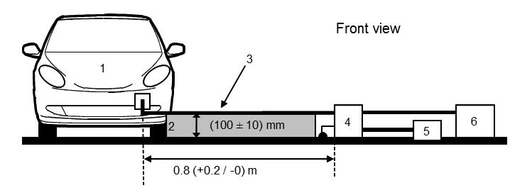
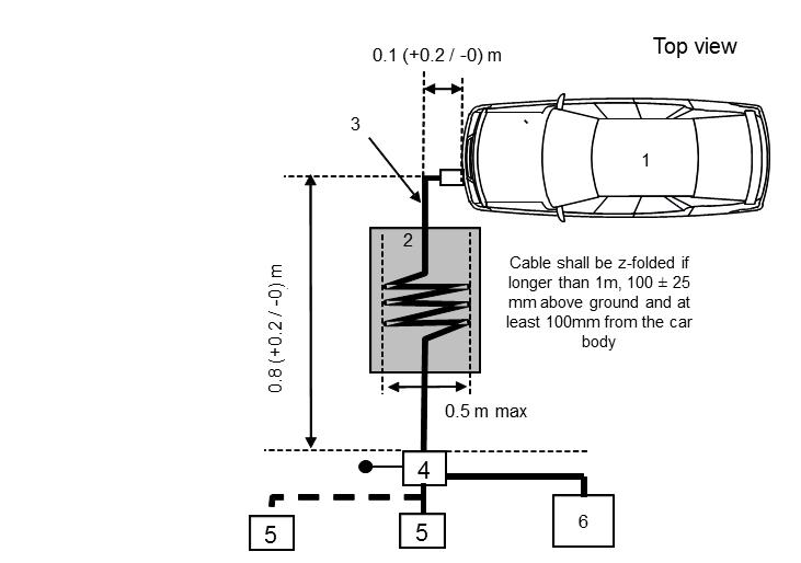
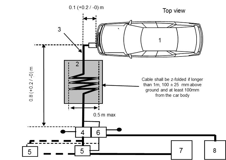
Legend: 1 Vehicle under test 2 Insulating support 3 Charging / communication cable 4 AC or DC Artificial network(s) grounded (for AC or DC power lines) |
5 Power mains socket 6 Impedance stabilization(s) grounded (for communication lines) 7 Charging station 8 Measuring receiver |
|
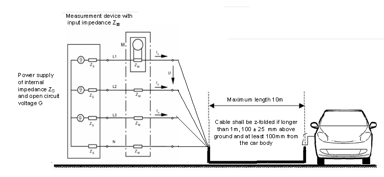
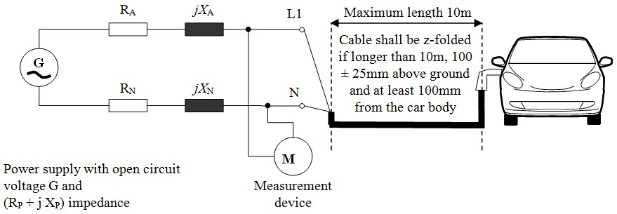
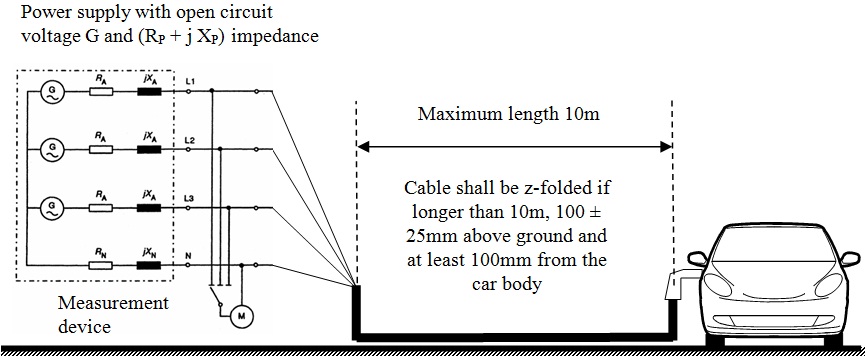
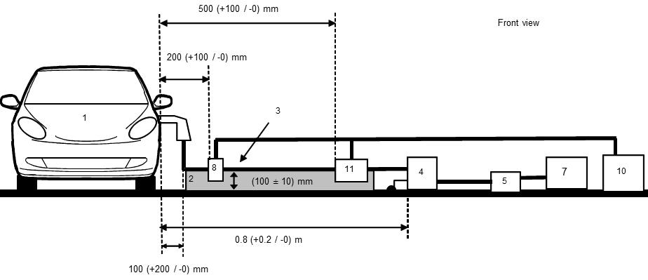
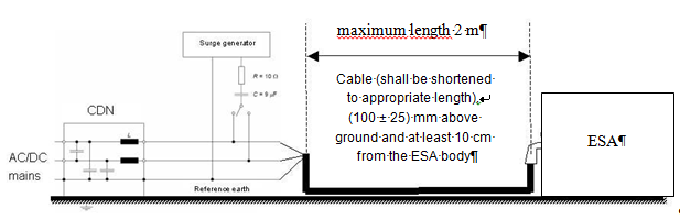
Legend: 1 Vehicle under test 2 Insulating support 3 Charging / communication cable 4 AC or DC Artificial network(s) grounded (for AC or DC power lines) 5 Power mains socket |
7 Charging station 8 Current probe 9 Communication lines 10 Measuring receiver 11 Capacitive voltage probe |
|
Legend: 1 Vehicle under test 2 Insulating support 3 Charging / communication cable 4 AC or DC Artificial network(s) grounded (for AC or DC power lines) 5 Power mains socket |
7 Charging station 8 Current probe (or capacitive voltage probe) 9 Communication lines 10 Measuring receiver 11 Capacitive voltage probe |
|
"REESS charging mode" vehicle test conditions |
Failure criteria |
|
The REESS shall be in charging mode. The state of charge (SOC) of the traction battery shall be kept between 20 per cent and 80 per cent of the maximum SOC during the whole time duration of the measurement (this may lead to the measurement being split into different time slots with the need to discharge the vehicle’s traction battery before starting the next time slot). If the current consumption can be adjusted, then the current shall be set to at least 20 per cent of its nominal value. |
Vehicle sets in motion |

|
" REESS charging mode" vehicle test conditions |
Failure criteria |
|
The REESS shall be in charging mode. The state of charge (SOC) of the traction battery shall be kept between 20 per cent and 80 per cent of the maximum SOC during the whole time duration of the measurement (this may lead to the measurement being split into different time slots with the need to discharge the vehicle’s traction battery before starting the next time slot).. If the current consumption can be adjusted, then the current shall be set to at least 20 per cent of its nominal value. |
Vehicle sets in motion |

|
Frequency
range |
Peak detector |
Quasi-peak detector |
Average detector |
|||
|
RBW at |
Scan |
RBW at |
Scan |
RBW at |
Scan |
|
|
0.15 to 30 |
9/10 kHz |
10 s/MHz |
9 kHz |
200 s/MHz |
9/10 kHz |
10 s/MHz |
|
Frequency range |
Peak detector |
Quasi-peak detector |
Average detector |
||||||
|
BW
at |
Step |
Dwell time |
BW
at |
Step |
Dwell time |
BW
at |
Step |
Dwell time |
|
|
0.15 to 30 |
9 kHz |
5 kHz |
50 ms |
9 kHz |
5 kHz |
1 s |
9 kHz |
5 kHz |
50 ms |
|
Frequency
range |
Peak detector |
Quasi-peak detector |
Average detector |
|||
|
RBW
at |
Scan |
RBW
at |
Scan |
RBW
at |
Scan |
|
|
0.15 to 30 |
9/10 kHz |
10 s/MHz |
9 kHz |
200 s/MHz |
9/10 kHz |
10 s/MHz |
|
Frequency range |
Peak detector |
Quasi-peak detector |
Average detector |
||||||
|
BW at |
Step |
Dwell time |
BW at |
Step |
Dwell time |
BW at |
Step |
Dwell time |
|
|
0.15 to 30 |
9 kHz |
5 kHz |
50 ms |
9 kHz |
5 kHz |
1 s |
9 kHz |
5 kHz |
50 ms |
|
"REESS charging mode" ESA test conditions |
Failure criteria |
|
ESA shall be in configuration "REESS charging mode coupled to the power grid". The state of charge (SOC) of the traction battery shall be kept between 20 per cent and 80 per cent of the maximum SOC during the whole time duration of the measurement (this may lead to the measurement being split into different time slots with the need to discharge the vehicle’s traction battery before starting the next time slot). If the current consumption can be adjusted, then the current shall be set to at least 20 per cent of its nominal value. |
Incorrect
charging condition |
|
"REESS charging mode" ESA test conditions |
Failure criteria |
|
ESA shall be in configuration "REESS charging mode coupled to the power grid". The state of charge (SOC) of the traction battery shall be kept between 20 per cent and 80 per cent of the maximum SOC during the whole frequency range measurement (this may lead to split the measurement in different sub-bands with the need to discharge the vehicle's traction battery before starting the next sub-bands). If the test is not performed with a REESS the ESA should be tested at rated current. If the current consumption can be adjusted, then the current shall be set to at least 20 per cent of its nominal value. |
Incorrect
charging condition |
|
|
Maximum allowed pulse amplitude for |
|
|
Polarity of pulse amplitude |
Vehicles with 12 V systems |
Vehicles with 24 V systems |
|
Positive |
+75 V |
+150 V |
|
Negative |
–100 V |
–450 V |
|
Test pulse number |
Immunity test level |
Functional status for systems: |
|
|
Related to immunity related functions |
Not related to immunity related functions |
||
|
1 |
III |
C |
D |
|
2a |
III |
B |
D |
|
2b |
III |
C |
D |
|
3a/3b |
III |
A |
D |
|
4 |
III |
B (for ESA which shall be operational during engine start phases) C (for other ESA) |
D |
|
Harmonic number n |
Maximum authorized harmonic current A |
|
Odd harmonics |
|
|
3 |
2.3 |
|
5 |
1.14 |
|
7 |
0.77 |
|
9 |
0.40 |
|
11 |
0.33 |
|
13 |
0.21 |
|
15 ≤ n ≤ 39 |
0.15x15/n |
|
Even harmonics |
|
|
2 |
1.08 |
|
4 |
0.43 |
|
6 |
0.30 |
|
8 ≤ n ≤ 40 |
0.23x8/n |
|
Minimum Rsce |
Acceptable
individual harmonic current In/I1 |
Maximum
current harmonic ratio |
||||||
|
|
I3 |
I5 |
I7 |
I9 |
I11 |
I13 |
THD |
PWHD |
|
33 |
21.6 |
10.7 |
7.2 |
3.8 |
3.1 |
2 |
23 |
23 |
|
66 |
24 |
13 |
8 |
5 |
4 |
3 |
26 |
26 |
|
120 |
27 |
15 |
10 |
6 |
5 |
4 |
30 |
30 |
|
250 |
35 |
20 |
13 |
9 |
8 |
6 |
40 |
40 |
|
≥ 350 |
41 |
24 |
15 |
12 |
10 |
8 |
47 |
47 |
|
Relative values of even harmonics lower or equal to 12 shall be lower than 16/n %. Even harmonics greater than 12 are taken into account in the Total Harmonic Distorsion (THD) and Partial Weighted Harmonic Distorsion (PWHD) the same way than odd harmonics. Linear interpolation between successive values of Short Circuit Ratio of an Equipment (Rsce) is authorized. |
||||||||
|
Minimum Rsce |
Acceptable
individual harmonic current In/I1 |
Maximum
current harmonic ratio |
||||
|
|
I5 |
I7 |
I11 |
I13 |
THD |
PWHD |
|
33 |
10.7 |
7.2 |
3.1 |
2 |
13 |
22 |
|
66 |
14 |
9 |
5 |
3 |
16 |
25 |
|
120 |
19 |
12 |
7 |
4 |
22 |
28 |
|
250 |
31 |
20 |
12 |
7 |
37 |
38 |
|
≥ 350 |
40 |
25 |
15 |
10 |
48 |
46 |
|
Relative values of even harmonics lower or equal to 12 shall be lower than 16/n %. Even harmonics greater than 12 are taken into account in the THD and PWHD the same way than odd harmonics. Linear interpolation between successive values of Rsce is authorized. |
||||||
|
Minimum Rsce |
Acceptable individual harmonic current In/I1 % |
Maximum current harmonic ratio % |
||||
|
|
I5 |
I7 |
I11 |
I13 |
THD |
PWHD |
|
33 |
10.7 |
7.2 |
3.1 |
2 |
13 |
22 |
|
≥ 120 |
40 |
25 |
15 |
10 |
48 |
46 |
|
Relative values of even harmonics lower or equal to 12 shall be lower than 16/n %. Even harmonics greater than 12 are taken into account in the THD and PWHD the same way than odd harmonics |
||||||
|
Frequency (MHz) |
Limits and detector |
|
0.15 to 0.5 |
66 to 56 dBµV (quasi-peak) 56 to 46 dBµV (average) (linearly decreasing with logarithm of frequency) |
|
0.5 to 5 |
56 dBµV (quasi-peak) 46 dBµV (average) |
|
5 to 30 |
60 dBµV (quasi-peak) 50 dBµV (average) |
|
Frequency (MHz) |
Limits and detector |
|
0.15 to 0.5 |
79 dBµV (quasi-peak) 66 dBµV (average) |
|
0.5 to 30 |
73 dBµV (quasi-peak) 60 dBµV (average) |
|
Frequency (MHz) |
Voltage limits (detector) |
Current limits (detector) |
|
0.15 to 0.5 |
84 to 74 dBµV (quasi-peak) 74 to 64 dBµV (average) |
40 to 30 dBµA (quasi-peak) 30 to 20 dBµA (average) |
|
0.5 to 30 |
74 dBµV (quasi-peak) 64 dBµV (average) |
30 dBµA (quasi-peak) 20 dBµA (average) |
|
Harmonic number n |
Maximum authorized harmonic current A |
|
Odd harmonics |
|
|
3 |
2.3 |
|
5 |
1.14 |
|
7 |
0.77 |
|
9 |
0.40 |
|
11 |
0.33 |
|
13 |
0.21 |
|
15 ≤ n ≤ 39 |
0.15x15/n |
|
Even harmonics |
|
|
2 |
1.08 |
|
4 |
0.43 |
|
6 |
0.30 |
|
8 ≤ n ≤ 40 |
0.23x8/n |
|
Minimum Rsce |
Acceptable individual harmonic current In/I1 % |
Maximum current harmonic ratio % |
||||||
|
I3 |
I5 |
I7 |
I9 |
I11 |
I13 |
THD |
PWHD |
|
|
33 |
21.6 |
10.7 |
7.2 |
3.8 |
3.1 |
2 |
23 |
23 |
|
66 |
24 |
13 |
8 |
5 |
4 |
3 |
26 |
26 |
|
120 |
27 |
15 |
10 |
6 |
5 |
4 |
30 |
30 |
|
250 |
35 |
20 |
13 |
9 |
8 |
6 |
40 |
40 |
|
≥ 350 |
41 |
24 |
15 |
12 |
10 |
8 |
47 |
47 |
|
Relative values of even harmonics lower or equal to 12 shall be lower than 16/n %. Even harmonics greater than 12 are taken into account in the THD and PWHD in the same way than odd harmonics. Linear interpolation between successive values of Rsce is authorized. |
||||||||
|
Minimum Rsce |
Acceptable individual harmonic current In/I1 % |
Maximum current harmonic ratio % |
||||
|
I5 |
I7 |
I11 |
I13 |
THD |
PWHD |
|
|
33 |
10.7 |
7.2 |
3.1 |
2 |
13 |
22 |
|
66 |
14 |
9 |
5 |
3 |
16 |
25 |
|
120 |
19 |
12 |
7 |
4 |
22 |
28 |
|
250 |
31 |
20 |
12 |
7 |
37 |
38 |
|
≥ 350 |
40 |
25 |
15 |
10 |
48 |
46 |
|
Relative values of even harmonics lower or equal to 12 shall be lower than 16/n %. Even harmonics greater than 12 are taken into account in the THD and PWHD in the same way as odd harmonics. Linear interpolation between successive values of Rsce is authorized. |
||||||
|
Minimum Rsce |
Acceptable individual harmonic current In/I1 % |
Maximum current harmonic ratio % |
||||
|
I5 |
I7 |
I11 |
I13 |
THD |
PWHD |
|
|
33 |
10.7 |
7.2 |
3.1 |
2 |
13 |
22 |
|
≥ 120 |
40 |
25 |
15 |
10 |
48 |
46 |
|
Relative values of even harmonics lower or equal to 12 shall be lower than 16/n %. Even harmonics greater than 12 are taken into account in the THD and PWHD in the same way as odd harmonics. |
||||||
|
Frequency (MHz) |
Limits and detector |
|
0.15 to 0.5 |
66 to 56 dBµV (quasi-peak) (linearly decreasing with logarithm of frequency) |
|
0.5 to 5 |
56 dBµV (quasi-peak) |
|
5 to 30 |
60 dBµV (quasi-peak) |
|
Frequency (MHz) |
Limits and detector |
|
0.15 to 0.5 |
79 dBµV (quasi-peak) |
|
0.5 to 30 |
73 dBµV (quasi-peak) |
|
Frequency (MHz) |
Voltage limits (detector) |
Current limits (detector) |
|
0.15 to 0.5 |
84 to 74 dBµV (quasi-peak) (linearly decreasing with |
40 to 30 dBµA (quasi-peak) (linearly decreasing with |
|
0.5 to 30 |
74 dBµV (quasi-peak) |
30 dBµA (quasi-peak) |
|
|
Maximum allowed pulse amplitude for |
|
|
Polarity of pulse amplitude |
Vehicles with 12 V systems |
Vehicles with 24 V systems |
|
Positive |
+75 V |
+150 V |
|
Negative |
–100 V |
–450 V |
|
Test pulse number |
Immunity test level |
Functional status for systems: |
|
|
Related to immunity related functions |
Not related to immunity related functions |
||
|
1 |
III |
C |
D |
|
2a |
III |
B |
D |
|
2b |
III |
C |
D |
|
3a/3b |
III |
A |
D |
|
4 |
III |
B (for ESA which shall be operational during engine start phases) C (for other ESA) |
D |
|
Limit E (dBµV/m) at frequency F (MHz) |
||
|
3 |
75-400 MHz |
400-1,000 MHz |
|
E = 32 |
E = 32 + 15.13 log (F/75) |
E = 43 |
|
Limit E (dBµV/m) at frequency F (MHz) |
||
|
30-75 MHz |
75-400 MHz |
400-1,000 MHz |
|
E = 42 |
E = 42 + 15.13 log (F/75) |
E = 53 |
|
Limit E (dBµV/m) at frequency F (MHz) |
||
|
30-75 MHz |
75-400 MHz |
400-1,000 MHz |
|
E = 22 |
E = 22 + 15.13 log (F/75) |
E = 33 |
|
Limit E (dBµV/m) at frequency F (MHz) |
||
|
30-75 MHz |
75-400 MHz |
400-1,000 MHz |
|
E = 32 |
E = 32 + 15.13 log (F/75) |
E = 43 |
|
Limit E (dBµV/m) at frequency F (MHz) |
||
|
30-75 MHz |
75-400 MHz |
400-1,000 MHz |
|
E = 62 - 25.13 log (F/30) |
E = 52 + 15.13 log (F/75) |
E = 63 |
|
Limit E (dBµV/m) at frequency F (MHz) |
||
|
30-75 MHz |
75-400 MHz |
400-1,000 MHz |
|
E = 52 - 25.13 log (F/30) |
E = 42 + 15.13 log (F/75) |
E = 53 |
|
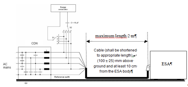
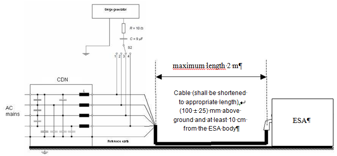
Legend |
C2: 0.1 µF |
|
L1: 5 µH |
R1: 1 kΩ |
|
C1: 0.1 µF |
R2: 1 MΩ (discharging C2 to < 50 Vdc within 60 s) |
|
|
|
|
|
Frequency bands [Hz] |
Max. output power [W] |
Antenna position at
vehicle, |
|
Frequency
range |
Peak detector |
Quasi-peak detector |
Average detector |
|||
|
RBW at |
Scan |
RBW at |
Scan |
RBW at |
Scan |
|
|
30
to |
100/120 kHz |
100 ms/MHz |
120 |
20 |
100/120 kHz |
100 ms/MHz |
|
Frequency
range |
Peak detector |
Quasi-peak detector |
Average detector |
||||||
|
BW at |
Step |
Dwell time |
BW at |
Step |
Dwell time |
BW at |
Step |
Dwell time |
|
|
30 to 1,000 |
120 kHz |
50 |
5 |
120 |
50 |
1 |
120 |
50 |
5 |
|
Frequency
range |
Peak detector |
Quasi-peak detector |
Average detector |
|||
|
RBW at |
Scan |
RBW at |
Scan |
RBW at |
Scan |
|
|
30 to 1,000 |
100/120 kHz |
100 ms/MHz |
120 kHz |
20 s/MHz |
100/120 kHz |
100 ms/MHz |
|
Frequency
range |
Peak detector |
Quasi-peak detector |
Average detector |
||||||
|
BW
at |
Step |
Dwell time |
BW
at |
Step |
Dwell time |
BW
at |
Step |
Dwell time |
|
|
30 to 1,000 |
120 kHz |
50 kHz |
5 |
120 kHz |
50 kHz |
1 |
120 kHz |
50 kHz |
5 |
|
"50 km/h cycle" vehicle test conditions |
Failure criteria |
|
Vehicle speed 50 km/h (respectively 25 km/h for L1, L2 vehicles) 20 per cent (vehicle driving the rollers). If the vehicle is equipped with a cruise control system, it shall be operational. |
Speed variation greater than 10 per cent of the nominal speed. In case of automatic gearbox: change of gear ratio inducing a speed variation greater than 10 per cent of the nominal speed. |
|
Dipped beams ON (manual mode) |
Lighting OFF |
|
Front wiper ON (manual mode) maximum speed |
Complete stop of front wiper |
|
Direction indicator on driver's side ON |
Frequency change (lower than 0.75 Hz or greater than 2.25 Hz). Duty cycle change (lower than 25 per cent or greater than 75 per cent). |
|
Adjustable suspension in normal position |
Unexpected significant variation |
|
Driver's seat and steering wheel in medium position |
Unexpected variation greater than 10 per cent of total range |
|
Alarm unset |
Unexpected activation of alarm |
|
Horn OFF |
Unexpected activation of horn |
|
Airbag and safety restraint systems operational with inhibited passenger airbag if this function exists |
Unexpected activation |
|
Automatic doors closed |
Unexpected opening |
|
Adjustable endurance brake lever in normal position |
Unexpected activation |
|
"Brake cycle" vehicle test conditions |
Failure criteria |
|
To be defined in brake cycle test plan. This shall include operation of the brake pedal (unless there are technical reasons not to do so) but not necessarily an anti-lock brake system action. |
Stop
lights inactivated during cycle |
|
"REESS charging mode" vehicle test conditions |
Failure criteria |
|
The REESS shall be in charging mode. The REESS State of charge (SOC) shall be kept between 20 per cent and 80 per cent of the maximum SOC during the whole frequency range measurement (this may lead to split the measurement in different sub-bands with the need to discharge the vehicle's traction battery before starting the next sub-bands). If the current consumption can be adjusted, then the current shall be set to at least 20 per cent of its nominal value. |
Vehicle sets in motion. |
|
Frequency
range |
Peak detector |
Quasi-peak detector |
Average detector |
|||
|
RBW at |
Scan |
RBW at |
Scan |
RBW at |
Scan |
|
|
30 to 1,000 |
100/120 kHz |
100 ms/MHz |
120 kHz |
20 s/MHz |
100/120 kHz |
100 ms/MHz |
|
Frequency
range |
Peak detector |
Quasi-peak detector |
Average detector |
||||||
|
BW
at |
Step |
Dwell time |
BW
at |
Step |
Dwell time |
BW
at |
Step |
Dwell time |
|
|
30 to 1,000 |
120 Hz |
50 kHz |
5 ms |
120 Hz |
50 kHz |
1 s |
120 kHz |
50 kHz |
5 ms |
|
Legend: 1 ESA (grounded locally if required in test plan) 2 LV Test harness 3 LV Load simulator (placement and ground connection according to CISPR 25 paragraph 6.4.2.5) 4 Power supply (location optional) 5 LV Artificial network (AN) 6 Ground plane (bonded to shielded enclosure) 7 Low relative permittivity support (εr ≤ 1.4) 8 Biconical antenna 10 High-quality coaxial cable e.g. double-shielded (50 Ω) 11 Bulkhead connector 12 Measuring instrument
|
13 RF absorber material 14 Stimulation and monitoring system 15 HV harness 16 HV load simulator 17 HV AN 18 HV power supply 19 HV feed-through 25 AC/DC charger harness 26 AC/DC load simulator (e.g. Programmable Logic Controller (PLC)) 27 50µH Line Impedance Stabilization Network (LISN) (AC) or HVAN (DC) 28 AC/DC power supply 29 AC/DC feed-through |
|
Frequency
range |
Peak detector |
Quasi-peak detector |
Average detector |
|||
|
RBW
at |
Scan |
RBW
at |
Scan
|
RBW
at |
Scan |
|
|
30 to 1,000 |
100/120 kHz |
100 ms/MHz |
120 kHz |
20 s/MHz |
100/120 kHz |
100 ms/MHz |
|
Frequency
range |
Peak detector |
Quasi-peak detector |
Average detector |
||||||||
|
BW at |
Step |
Dwell time |
BW at |
Step |
Dwell time |
BW at |
Step |
Dwell time |
|||
|
30 to 1,000 |
120 kHz |
50 kHz |
5 ms |
120 kHz |
50 kHz |
1 s |
120 kHz |
50 kHz |
5 ms |
||
|
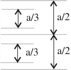
Upper frequency |
Cell
form factor |
Cell
form factor |
Plate
separation |
Septum
|
|
200 200 |
1.69 1.00 |
0.66 1 |
56 60 |
70 50 |
|
Legend: 1 ESA (grounded locally if required in test plan) 2 LV Test harness 3 LV Load simulator (placement and ground connection according to CISPR 25 paragraph 6.4.2.5.) 4 Power supply (location optional) 5 LV Artificial network (AN) 6 Ground plane (bonded to shielded enclosure) 7 Low relative permittivity support (εr ≤ 1.4) 8 Horn antenna 10 High-quality coaxial cable e.g. double-shielded (50 Ω) 11 Bulkhead connector 12 RF signal generator and amplifier
|
13 RF absorber material 14 Stimulation and monitoring system 15 HV harness 16 HV load simulator 17 HV AN 18 HV power supply 19 HV feed-through 25 AC/DC charger harness 26 AC/DC load simulator (e.g. PLC) 27 50µH LISN (AC) or HVAN (DC) 28 AC/DC power supply 29 AC/DC feed-through |
|
Legend: 1 ESA (grounded locally if required in test plan) 2 LV Test harness 3 LV supply 4 LV LISN 5 LV load simulator 6 Stimulation and monitoring system 7 Low relative permittivity support 8 Ground plane 9 Injection probe 10 RF signal amplifier and generator |
11 HV DC harness 12 HV AN 13 HV DC load 14 HV DC feed-through 15 HV DC load simulator 16 HV AC/DC charger harness 17 50 µH LISN (AC) or HV AN (DC) 18 HV AC/DC power supply 19 HV AC/DC feed-through 20 HV AC/DC load simulator (e.g. PLC) |